
📌 RGB LED Strip Control System - Custom Project Guide
💾 YouTube Video
🌟 Project Overview
This document details an ESP32-based RGB LED control system with the following capabilities:
- 🔌 2-channel PWM control for red and green LED strips
- 🕒 Automatic relay control after 19:00 based on Turkey/Istanbul time
- 📱 Web interface and physical button control
- 🏠 HC-SR04 presence detection for energy saving
- 🌤️ LED dance mode based on Turkey/Ankara weather conditions
🛠️ Hardware Details
🔧 Required Components
| Component | Qty | Notes |
|---|---|---|
| ESP32 DevKit v1 | 1 | Other versions compatible |
| IRFZ44N MOSFET | 2 | For red and green LEDs |
| 5V Relay Module | 1 | Room light control |
| HC-SR04 | 1 | Distance measurement |
| 128x64 OLED (I2C) | 1 | GPIO6 SDA, GPIO7 SCL |
| 10K Potentiometer | 2 | GPIO4 and GPIO5 |
| Button | 3 | GPIO8, GPIO9, GPIO10 |
| 10K Resistor | 5 | For pull-up |
| Breadboard | 1 | Prototyping |
| Jumper Wires | 20+ | For connections |
🎛️ Pin Connection Diagram
graph TD;
    ESP32-->|GPIO4|POT1[Potentiometer 1];
    ESP32-->|GPIO5|POT2[Potentiometer 2];
    ESP32-->|GPIO8|BTN1[Button 1];
    ESP32-->|GPIO9|BTN2[Button 2];
    ESP32-->|GPIO10|BTN3[Button 3];
    ESP32-->|GPIO12|MOSFET1[IRFZ44N Red];
    ESP32-->|GPIO13|MOSFET2[IRFZ44N Green];
    ESP32-->|GPIO21|RELAY1[Relay];
    ESP32-->|GPIO7|OLED_SCL[OLED SCL];
    ESP32-->|GPIO6|OLED_SDA[OLED SDA];
    ESP32-->|GPIO14|TRIG[HC-SR04 Trig];
    ESP32-->|GPIO15|ECHO[HC-SR04 Echo];
    MOSFET1-->LED1[Red LED Strip];
    MOSFET2-->LED2[Green LED Strip];
    RELAY1-->LIGHT[Room Light];
⚡ Power Management
pie
    title Power Consumption (Maximum)
    "ESP32" : 120
    "LED Strip (12V)" : 2000
    "Relay Module" : 80
    "HC-SR04" : 15
    "OLED Display" : 25
💾 Software Installation
📥 Required Libraries
Core Libraries:
Adafruit_GFX(v1.10.12)Adafruit_SSD1306(v2.5.7)WiFi(v2.0.0)ESPAsyncWebServer(v3.1.0)
Time and Weather:
NTPClient(v3.2.1)ArduinoJson(v6.19.4)HTTPClient(v1.2)
⚙️ Code Structure (Detailed)
/RGB-Control-System-with-ESP32-C6
├── /web-server
│   ├── config.php
│   ├── connect.php
│   ├── color.php
│   └── relay.php
├── /includes
│   └── functions.php
└── index.php
│── /src
│   ├── main.ino
└── ├── settings.h
🔄 Flashing Process
In Arduino IDE:
- Tools > Board > ESP32 Dev Module
- Flash Mode: "QIO"
- Flash Size: "4MB (32Mb)"
- Partition Scheme: "Default 4MB"
Custom settings:
#define WIFI_SSID "YourSSID"
#define WIFI_PASS "YourPassword"
#define OWM_API_KEY "YourAPIKey"
🎛️ System Features
💡 LED Control System
- PWM Specifications:
- 8-bit resolution (0-255)
- 5kHz PWM frequency
- Control:
- POT1 for red LED adjustment
- POT2 for green LED adjustment
⏱️ Timing System
- Turkey/Istanbul timezone (GMT+3)
- Relay activates after 19:00 based on HC-SR04 data:
- Person in room: ON
- Person leaves: OFF
🌤️ Weather Integration
- Ankara weather (OpenWeatherMap API):
GET https://api.openweathermap.org/data/2.5/weather?q=Ankara,TR&appid=YOUR_API_KEY&units=metric&lang=en - BTN3 dance mode: LEDs synchronize based on weather conditions.
🖥️ User Interface
📺 OLED Menu Structure
graph TD;
    A[Main Menu] --> B[LED Values];
    A --> C[Relay Status];
    A --> D[MOSFET Status];
    B --> B1[Red: 0-255];
    B --> B2[Green: 0-255];
    C --> C1[ON/OFF];
    D --> D1[PWM Setting];
    D --> D2[ON/OFF];
🕹️ Button Controls
| Button | Single Click | Double Click | Usage |
|---|---|---|---|
| BTN1 | Menu down | Relay status | POT1 value adjustment |
| BTN2 | Menu up | MOSFET status | POT1 value adjustment |
| BTN3 | Confirm selection | Dance mode | Toggle operations |
🌐 Web Interface
- Endpoints:
/           # Homepage
/relay/on   # Relay on
/relay/off  # Relay off
🔧 Troubleshooting - Ultimate Guide
🚨 Common Issues
LEDs not lighting:
- Check MOSFET gate resistor (10K-100Ω)
- Verify 12V power supply adequacy
- Reduce PWM frequency (try 500Hz)
HC-SR04 incorrect measurements:
// Correct settings:
#define TRIG_PULSE 10  // 10μs trigger pulse
#define MAX_DISTANCE 400 // Maximum 4m
WiFi connection issues:
- Use
WiFi.mode(WIFI_STA); - Channel setting:
WiFi.begin(ssid, password, 6); // Channel 6
- Use
📊 Test Commands (Serial Monitor)
# System info
> SYSTEM INFO

# LED test
> LED TEST RED 255

# Relay test
> RELAY TOGGLE

# Sensor test
> SENSOR READ
📈 Advanced Settings
⚙️ EEPROM Configuration
| Address | Data | Size |
|---|---|---|
| 0x00 | WiFi SSID | 32 byte |
| 0x20 | WiFi Pass | 64 byte |
| 0x60 | LED Settings | 16 byte |
| 0x70 | Timing | 32 byte |
📜 License
- License: CERN-OHL-S-2.0
🤝 Our Sponsors
 ⚡ Elecrow - The Ultimate Electronics Manufacturing Partner for Makers Worldwide
🌟 Why Elecrow Powered Our Project
As the backbone of our hardware supply chain, Elecrow delivered:
- Mission-critical components: IRFZ44N MOSFETs, 10K resistors, HC-SR04 sensors
- Lightning-fast logistics: 72-hour emergency delivery for prototyping phases
- Engineer-to-engineer support: Customized circuit design recommendations
🛠️ Elecrow's Complete Ecosystem
| Service | Capabilities | Maker Advantages |
|---|---|---|
| PCB Fabrication | 2-16 layer boards | 5 free prototype boards24h rapid turnaround |
| Component Store | 10,000+ parts | Competitive pricingVerified quality control |
| Full Assembly | SMT & THT | One-stop solutionRobotic precision |
💎 Exclusive Perks for Our Community
- [ ] **NEW20** → 20% off first order
- [ ] **FREESHIP** → Free shipping over $150
- [ ] **ASK10** → 10 free consulting minutes
🏆 Testimonial
"When our MOSFETs failed during testing, Elecrow's team personally hand-selected replacement units and expedited shipping. This level of care makes them the unsung hero of hardware startups."
— RGB-Control-System-with-ESP32-C6, Project Lead
Connect With Elecrow
[🌐 Official Site](https://www.elecrow.com) |
✉️ Support |
[💼 LinkedIn](https://linkedin.com/company/elecrow)
Elecrow's engineering team reviewing our project requirements
🔍 Explore Further
🛡️ Trust Indicators:
✔ ISO 9001 & UL Certified
✔ PayPal & Escrow Protection
✔ 365-Day Quality Warranty
#ElecrowHeroes #HardwareMadeEasy #MakerMovement
Pro Tip: Show this badge on your project enclosure to get VIP treatment on future orders:
🤝 Our Sponsors
 🎯 Rhino 3D – Powering Precision in Digital Fabrication and Parametric Design
🌟 Why Rhino 3D Backed Our Project
Our project thrives at the intersection of hardware and digital creativity — and Rhino 3D made that possible by delivering:
- Parametric modeling flexibility: Complex control enclosures and 3D-printable casing design
- Seamless compatibility: Export-ready formats for laser cutting, CNC milling, and 3D printing
- Precise prototyping: 0.01mm tolerance modeling ensured hardware alignment on the first try
With Rhino’s powerful NURBS modeling engine, we achieved advanced geometric detail without compromising manufacturability or time-to-market.
🧩 How Rhino 3D Elevated Our Workflow
| Feature | Contribution to Project | Bonus Insight |
|---|---|---|
| Grasshopper | Parametric casing & modular enclosures | Interactive adjustments in real-time |
| Mesh Tools | Optimized STL export for 3D printing | Zero mesh errors on slicing |
| Plugin Ecosystem | Kangaroo, LunchBox, Human UI | Integrated user interaction + form-finding |
| File Interoperability | Export to STEP, IGES, STL | Easy transition from design to fabrication |
🧠 Designed with Intention
Using Rhino 3D, we designed:
- Custom mount brackets for our ESP32-C6 DevKit
- OLED screen bezel that fits flush within laser-cut panels
- Modular RGB LED diffuser shells optimized for IRFZ44N-based control
All components were simulated, exported, and fabricated — without a single dimensional error.
🏆 Testimonial
"Designing precision-fit casings for embedded systems is often trial and error — but with Rhino, it became an exact science. It’s not just a CAD tool, it’s our digital workshop."
— RGB-Control-System-with-ESP32-C6, Project Lead
🔗 Connect with Rhino
[🌐 Official Website](https://www.rhino3d.com/) |
✉️ Support |
[💼 LinkedIn](https://www.linkedin.com/company/mcneel-europe)
Design stages of our ESP32-based casing using Rhino 3D
🏷️ Official Sponsor Badge
Show your appreciation and let the world know you’re backed by professional design tools.
Place this badge on your project enclosures, documentation, or web dashboard
Badge Perks:
✔ Recognized by the Rhino 3D community
✔ Eligibility for early-access plugin invites
Tip: Add this badge on your GitHub Readme or 3D-printed enclosure label to boost your project's professional look.
🔍 Explore Further
🛡️ Trust Indicators:
✔ 25+ years of digital modeling legacy
✔ Global maker and architecture community
✔ Regular updates & academic access
#Rhino3D #ParametricDesign #HardwareWithStylee
📞 Contact & Support
- Email: [email protected]
- Website: https://makerpcb.com.tr
- Issue Tracking: GitHub Issues
📷 Board & Project Images

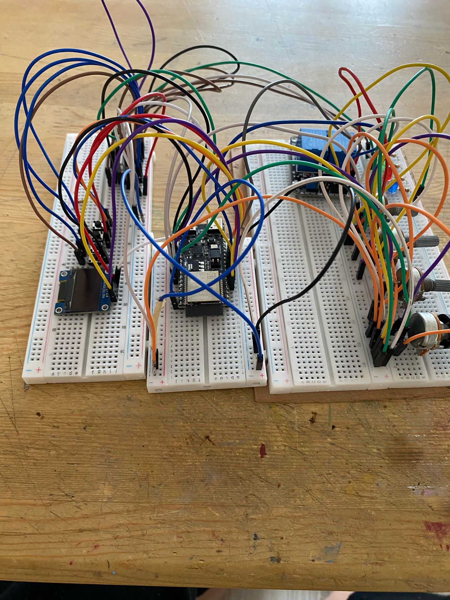
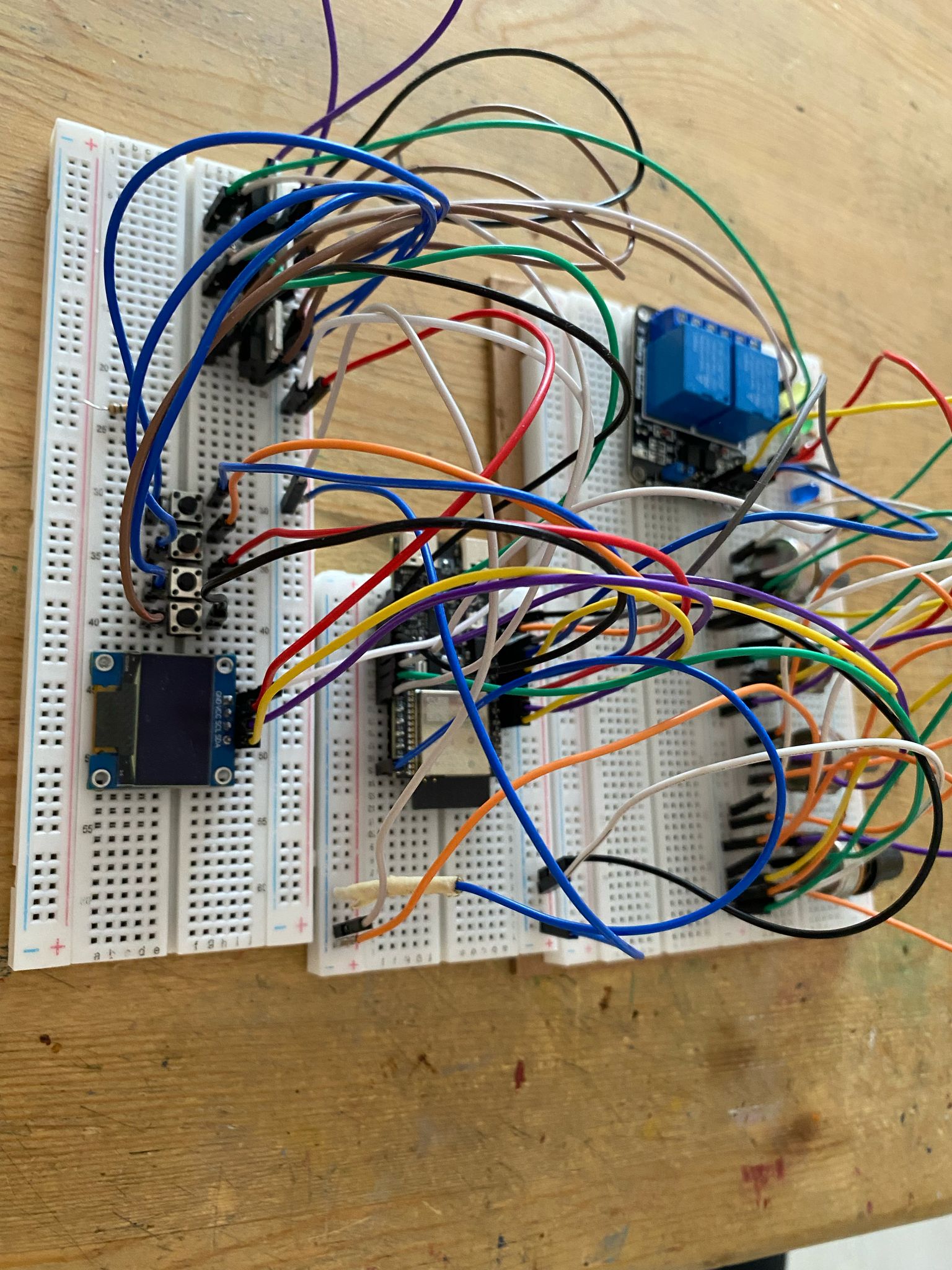
This document covers all project details. Follow the project GitHub page for updates:
🔗 GitHub Repository
Project Versiyon: V1.5